Packet Tracer Trivia Game
We would like to show you a description here but the site won’t allow us. Last night, I saw a person introduce the game in the forum. It looks very interesting;) Yes, of course you do! Thanks to the powerful visual simulation provided. Oct 15, 2009 Fill in your details below or click an icon to log in: Email (required) (Address never made public) Name (required).
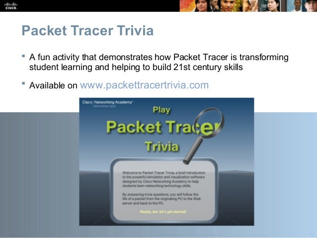
This page was exported from Free Cisco Training & Resources - Certification Exam Preparation Export date: Thu Feb 15 15: / +0000 GMT Cisco Networking Academy - Packet Tracer trivia game Last night, I saw a person introduce the game in the forum. It looks very interesting;) Yes, of course you do! Thanks to the powerful visual simulation provided by Packet Tracer, learning the fundamentals of how the Internet works is so much easier. Packet Tracer provides students with the ability to experience and explore the network without leaving their own desktop. We have designed this trivia game to engage participants in a short series of questions about the basic functions of the network, using Packet Tracer animations to illustrate the correct answers. The trivia game interface makes it fun while also providing a mechanism for communicating some key benefits of simulation software-enabled learning.
Packet Tracer is just one example of how Cisco Networking Academy is innovating learning for the 21st Century. We invite you to take a few minutes to play the trivia game now and then take a short survey to collect a special bonus prize. Also, visit the following links to learn more about Networking Academy. We hope you will find this a useful tool to spark the interest of not only current and prospective students, but also others who might be interested in Networking Academy more broadly.
It can serve as an example of the innovative learning tools and techniques employed by Networking Academy, and a demonstration of how Packet Tracer provides opportunities for 21st century learning:. Students who explore and experiment using Packet Tracer develop intellectual curiosity and critical thinking skills.
Packet Tracer's visually rich simulation environment facilitates comprehension of complex technology concepts. Students who troubleshoot networks using Packet Tracer develop problem solving skills. Students who design and build virtual networks using Packet Tracer improve their innovation and creativity skills. Students who explore concepts at their own pace in Packet Tracer's safe, virtual environment gain confidence in their decision making skills and abilities. Using Packet Tracer for team collaboration and competition activities builds social, communication, and negotiation skills.
Now you can play the, hoho Post date: 2009-05-26 11:34:53 Post date GMT: 2009-05-26 03:34:53 Post modified date: 2009-05-26 11:34:53 Post modified date GMT: 2009-05-26 03:34:53 Powered by Universal Post Manager plugin. HTML saving format developed by gVectors Team.

In our last chapter, we saw how to install Packet Tracer in both Windows and Linux. Now we will see how to use it. I have made this guide keeping absolute beginners in mind and when I say absolute beginners, I mean really absolute beginners. As part of this guide, we are going to create a star topology and see the difference between hub and a switch. Open Packet Tracer. On the lower left corner, there are all the components required for creating our network.
There are routers, switches, End devices, Hubs, Wireless Devices, and Connections etc. Click on “Hubs”. To the right, you should see types of hubs displayed. Click on the first type ‘Generic’, and drag your mouse to the workspace above and click on the point you want to place your hub as shown below. Click on the hub we just placed in our workspace. You are shown the physical view of the hub and it is a physical view literally.
You can even see the Power button of the hub. Click on the “Config” tab just beside the “Physical” tab. You are shown the global settings of the hub. You can change the display name of the hub.
Trivia Games Online Free
Change it from “Hub0” to “Hub”. Then close it. Now we are going to place five computers around the hub to form Hub and Spoke topology. From the components on the lower left corner click on “End devices”. From the options displayed, click on the first choice called “Generic” hold “CTRL” key and click on the workspace at five points around the hub where you want to place your computers. This is a shortcut to place many devices. Click on any “PC” we just placed.
Packet Tracer 7.0 Download
You should see something similar to “CPU”. This is the physical view of the PC. We can even see the Power button Click on the “Config” tab beside “Physical” tab.
On the global settings, change the name of the PC to “PC 2”. On gateway/ DNS select “DHCP”.
We will set up a DHCP server to assign IP addresses to the PC’s. You can have a look at other tabs beside “Config” tab. Perform this action for other PC’s also and name them differently. Then from “End Devices” select “Server” and place it on the workspace as below.
Click on “Server”. Go to “Config” tab. Here, we can configure Static IP address / Gateway / Subnet Mask. Click on the INTERFACE “FastEthernet0” to the left. Set IP configuration as static and give “IP address” as 192.168.0.254 and “ Subnet Mask” as “255.255.255.0”. Click on the GLOBAL “Settings” to the left. Set IP configuration as static and give “Gateway” as 192.168.0.1 and “DNS Server” as “8.8.8.8”. Go to “Services” tab.
We can see the services which can be configured on our servers HTTP, DHCP etc etc. Click on “DHCP”. Keep the Pool Name, change Default Gateway and DNS server same. Give “Starting IP address” as “192.168.0.10” and “Subnet Mask” as “255.255.255.0” and “Maximum number of Users” as “150”. Turn On DHCP service if it is OFF. Click on “Save”. Close the window. Now all we need is connecting our devices to create a network.
In the components to the lower left corner, Click on “Connections”. Different types of cabling are displayed. Here’s where Packet tracer assists in our learning abilities. If you are not sure what type of wiring to use, click on the first choice ‘automatic’.
Then on the workspace, click on “Server” and then click on the “Hub”. A connection is established. If the connection end points are red, then there is some problem with your wiring. If end points show green,then your wiring is alright.( We learn that we have to use copper straight through cabling in Star Topology.) Do the same for all connections as shown below. Request DHCP addressing for the PCs.
Click each PC and click the Desktop tab IP Configuration. Click DHCP and wait until the DHCP request is successful. After Configure Request DHCP addressing for all PCs, hover the mouse over the systems to check if IP addresses are assigned or not. Now let’s see the functioning of the hub. Click on “Simulation” beside “Real-time” as shown below. The Event List window will open. Click on “Edit Filters”.
We will see various protocols. Deselect “Show All/ None” option.
All options are deselected. Then Select ICMP option. What we are doing is trying to ping the machine. Close the Event List window. Click on “Add Simple PDU” as shown below. When we move the mouse on the workspace we can see a white envelope moving along with the mouse.
First click on the sending device( Click on “PC0” ). Then select the receiving device (Click on the “Server” ).
It should be clear to you that we are pinging the server from PC0. Our screen would look like below.
Now let us see how packets travel from PC0 to the Server we are trying to ping. Click on “Capture/ Forward” as shown below. Click on “Capture/ Forward” again. The ping travels from PC0 to the hub. Click on “Capture/ Forward” again.
The hub forwards the frame on all the ports, except the port through which the frame came in. All hosts except Server discard the frame since it is not addressed to them. Click on “Capture/ Forward”. The server forwards a frame to the hub. Click on “Capture/ Forward”. The hub once again forwards the frame on all ports except the input port. All hosts except PC0 discard it since it is not addressed to them.
The simulation success message is shown as below. To see the list of complete events undergone in this communication, Click on “Event List” as shown below. As already seen Hubs forward a frame they receive on all the outbound ports except the port through which it received the frame. When connected using hubs, the host devices share same bandwidth of the medium.
Since they share the same bandwidth, hosts can send frames at the same time on the medium which can result in collisions. In order to prevent frame collisions, Ethernet uses “Carrier Sense Multiple Access/ Collision detect (CSMA? Of course this prevents collisions but it still consumes a lot of bandwidth. The only solution is to this problem is to make the collision domain as small as possible. Let’s see how. Click on “Delete” as shown below. Click on the hub.
This will delete the hub and also the connections. Replace it with a “2960” switch and make the connections in the same way as done previously. Add a simple ICMP PDU as done previously. Click on “Capture/ Forward”. The first frame travels to the switch. Click on “Capture/ Forward” again.

The switch forwards the frame only to the Server, it’s intended destination. Subsequently the frame is forwarded to switch which forwards it to PC0 thus completing the communication. Now How does this happen? This happens because a switch creates only one collision domain per port forwarding frames only on the outbound port that reaches the destination of the frame. Since the hosts work in their own isolated collision domain, frames will never collide thus solving the problem of collisions. I think you now understood the working of not only hub and switch but also how to use Cisco Packet Tracer.
As we move further, we will see some of the practical examples.